


Introduction
The beginning of this project must date back to the summer of 2018. Montreal, Canada absolutely blooms in the summer but also sees at least a few weeks of sweltering hot humid days and nights. We don’t have an air conditioning unit, but we do have a ceiling fan in the bedroom, which we tend to turn on at night before going to bed… and consistently forget to turn off in the morning before going to work. Come home hours later to find the fan has been dutifully spinning all day. We appreciate its service at night so much that we consider it should have a break during the day. Of course, no one should have to actually remember to turn off the fan in the morning; this task is the bread and butter of a programmable timer, and a tantalizing home automation project!
The fan is not my property, and as such is out of limits for any physical tampering, up to and including “rig a Raspberry Pi to the damn thing”. Luckily though, it is also remote controlled, but by an unusual remote, since it is a radio remote, rather than infrared as you might expect.
The Remote (September 2018)
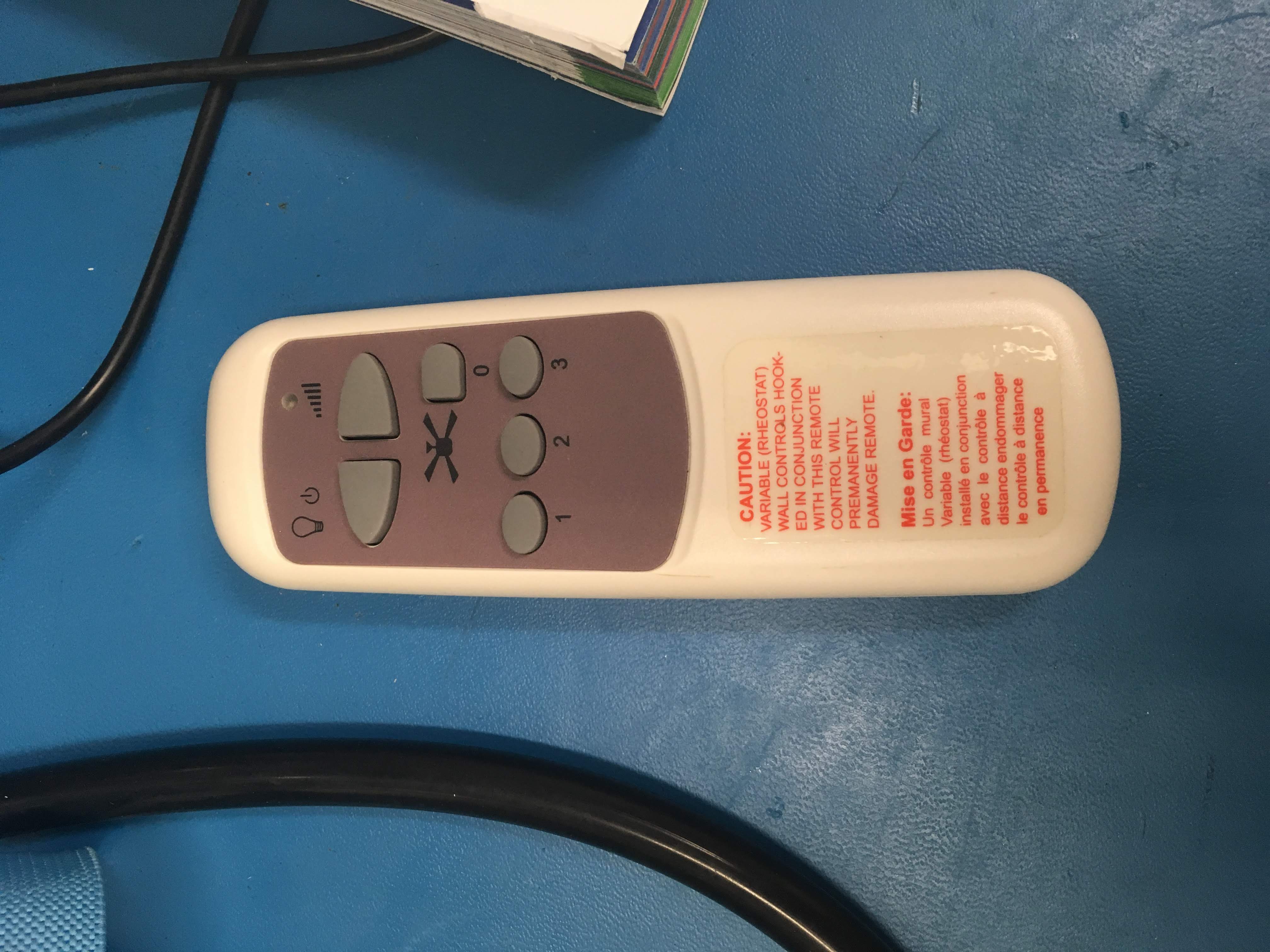
The back of the remote does reveal some information:
- FCC ID: KUJCE9001 (https://fccid.io/KUJCE9001)
- Model: BCF-0019X2 (https://www.google.com/search?q=BCF-0019X2)
The FCC filing is quite helpful, suggesting an operating frequency of 299.6 MHz (this turned out to be… approximate), offering a schematic diagram of the entire remote (encoder chip + simple RF transmitter), as well as the code table for each remote function button (light toggle, fan off, etc.)
The encoder chip is a fairly common and simple PT2262 compatible - 12 pulse-position modulation bits. Nothing fancy like rotating codes.
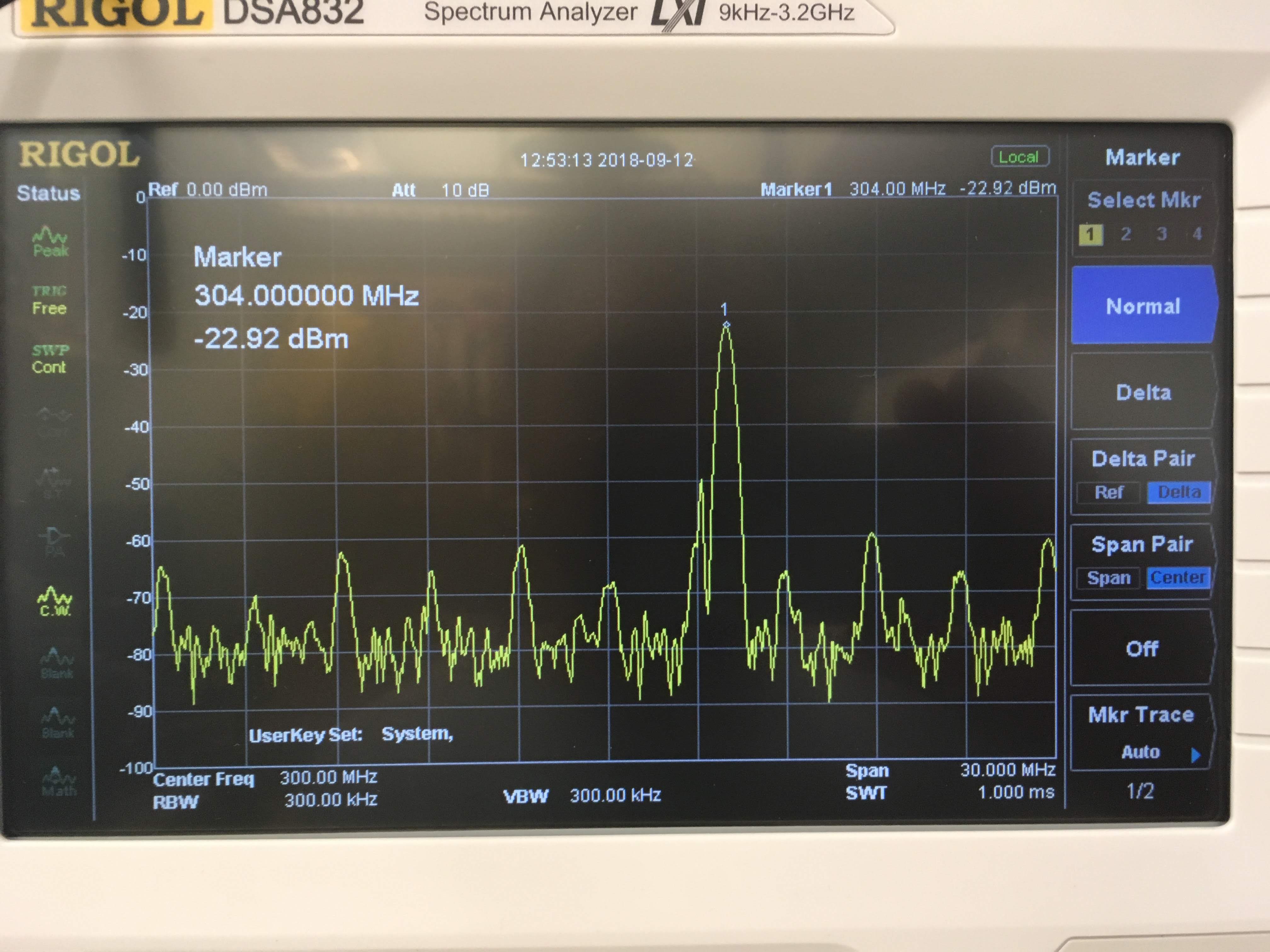
The real operating frequency turned out to be closer to 304 MHz. A friend suggests that the receiver is probably a simple design that tolerates a range of frequencies.
Option 1: Purchase a Second Remote and Modify It
The model number (“BCF-0019X2”) surfaces a few Amazon and eBay product pages, but all “unavailable” products. Unfortunately buying and modifying a working remote does not seem to be an option. Anyway retail prices appear to be around $25 USD, plus $10 or so for shipping, which felt like a bit much for this project, especially knowing the actual parts inside the remote (which must have added up to barely $1).
Option 2: Off-the-shelf Transmitter Module
While 315 MHz modules appear to be relatively easy to obtain (https://www.sparkfun.com/products/retired/8945), this is not the right frequency! Also, the 315 MHz modules tend to use SAW resonators which are manufactured for a specific frequency, so they cannot be easily modified to change the frequency.
Option 3: Off-the-shelf Transmitter Chip
Maxim offers a range of integrated RF components, such as the MAX1472 300MHz-to-450MHz Low-Power, Crystal-Based ASK Transmitter. This would offer a very reasonable price ($1.73) and (as far as I understand) excellent reliability, due to the PLL design. However, it only comes in surface mount package which are difficult to work with and requires a few other external components including a very specific crystal (1/32 of the output frequency, 9.375 MHz), which would probably be difficult to come by.
Option 4: Off-the-shelf Transceiver Board (May 2019)
After further research, I stumbled on the Semtech SX1276 137 MHz to 1020 MHz Long Range Low Power Transceiver. It’s designed to support a neat recent long-range communication technology called LoRa which promises kilobit per second data rate over several kilometers. That part wasn’t the point here though, rather the SX1276’s frequency synthesizer which appeared to cover several bands:
2.5.2. Frequency Synthesis
Table 7 Frequency Synthesizer Specification

Symbol  Description                 Conditions            Min Typ Max             Unit
FR      Synthesizer frequency range               Band 3  137     175 (*160)      MHz
                                     Programmable Band 2  410     525 (*480)
                                    (*for SX1279) Band 1  862 (*779) 1020 (*960)
The register programming guide suggested it might be possible to set arbitrary frequencies:
4.1.4. Frequency Settings
Recalling that the frequency step is given by:
  F_STEP = F_XOSC / 2^19
In order to set LO frequency values following registers are available.
F_RF is a 24-bit register which defines carrier frequency. The carrier frequency relates
to the register contents by following formula:
  R_FR = R_STEP * R_FR(23,0)
The SX1276 can be found in a variety of development boards, but Semtech’s own were quite expensive, and lacked a microcontroller, so were not too attractive.
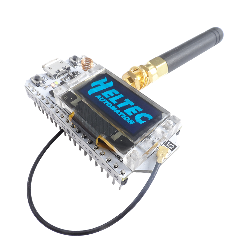
However, Heltec had an interesting offering in the WiFi LoRa 32 (V2) which combines an ESP32 microcontroller, SX1276, OLED display, micro USB interface and other conveniences for a mere $18. Bingo! That was the one!
After an excruciating month-long wait for delivery from China, the package finally arrived! The ESP32 is Arduino compatible and it was not too difficult to install the board into Arduino Development Environment.
I wrote a little code to program the SX1276, uploaded it to the ESP32, and… the RegIrqFlags1 PllLock bit never came on. 😞 It looks like the synthesizer can’t be tuned to arbitrary frequencies as I hoped. Back to the drawing board…
Option 5: Remote Control Duplicator
While browsing idly for alternatives, I stumbled on “remote control duplicators” on AliExpress. I can only assume these have a relatively flexible frequency hopping receiver, some memory, and an equally flexible transmitter. Take care that the frequency of your original remote is supported by the duplicator! Some claim support only for 433 MHz, others 868 MHz, and others claim a set of many supported bands. The price point is impressive ($10) and suggests how inexpensive integrated RF hardware has become.
One downside is that you will still need the original remote, even after recording the signal, if the duplicator loses the pattern or you need to replay a different command than was originally recorded.
And, er, I didn’t want to wait another month for shipping, and it’s less fun than making our own 🙂.
Option 6: Build a Transmitter from Discrete Parts
This was an option from the beginning but I had been avoiding it, as RF circuits are… outside of my comfort zone. RF circuits can be notoriously difficult to build and to debug. Due to high operating frequency (above 100 MHz or so), most of the common and inexpensive test equipment (multimeter, basic oscilloscope) are useless. Access to specialized RF test equipment (spectrum analyzer) makes things much easier.
Tool 1: Spectrum Analyzer
A spectrum analyzer is basically a receiver capable of very quickly “sweeping” across a range of frequencies and showing the signal strength at each frequency. It can help identify the transmission frequency of an unknown signal. Even a basic model is relatively expensive ($1000), but I do have occasional access to one, which is what I used to identify the remote control operating frequency above. However, I wasn’t able to use it while building my own circuit.
Tool 2: High Frequency Digital Oscilloscope
Danukeru has donated a Siglent SDS1202X-E oscilloscope to Foulab which turned out to be essential for my project. Nominally, the oscilloscope is rated for signals up to 200 MHz. However, I found that by increasing the vertical scale to maximum, I was able to pick up signals as high as 300 MHz. The oscilloscope must have relatively slow roll-off and the manufacturer only guarantees precision up to 200 MHz, but in reality the equipment can pick up signals a bit above that. This allowed me to check that my transmitter was working at all, and to make coarse frequency adjustments, but it’s not a good tool for measuring frequency precisely.
Tool 3: HackRF

A software defined radio (SDR) is also a very versatile receiver (and sometimes transmitter), with a very wide frequency range, but isn’t capable of sweeping quite as fast as a spectrum analyzer. In exchange, it’s able to capture very precise recordings of signals at fixed frequencies. This can be used to duplicate signals and emulate a range of different radio transmitters and receivers. They are usually around $100 and I didn’t have any future plans for one so I preferred not purchasing one.
However, chironex from The Thought Emporium does own a HackRF One which he has graciously lent me every time I asked. This turned out to be an indispensable tool for building my RF transmitter circuit.
SDR requires a computer and software to operate the device and there are many choices. Ultimately, my choices were determined by OS compatibility and convenience. I used Homebrew to install gqrx and Universal Radio Hacker, which worked well.
- gqrx is more geared towards a waterfall spectrum view, allowing you to track the frequency of a signal across a wide range.
- URH has a powerful signal analysis toolbox. Once a signal is captured, it helps decode the information encoded in the signal.
They do both have overlapping features (URH has a spectrum tool and vice-versa).
Tool 4: Build Your Own Radio Signal Sniffer (January 2020)
No good project is complete without a digression into building your own tools.
While researching designs for RF transmitter, I found this design for a VHF-UHF RF Sniffer. This would be a cheap home made alternative to an advanced signal analyzer, to confirm whether the transmitter was actually operating. I built one, but it turned out not to work very well, and ultimately turned to the HackRF for my debugging needs.
The RF Transmitter (February 2020)
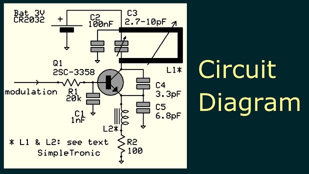
The design for the transmitter is simpletronic’s UHF Remote Control Transmitter. It’s a very simple single-transistor Colpitts oscillator, total part cost less than $5.
To understand the circuit, reason about it as two simultaneous circuits:
- DC: all voltages and currents are constant, capacitors are open-circuit (this simplifies the circuit considerably), and the only goal is to bias the transistor (set a particular base-emitter voltage and collector current.)
- AC: “small signal”, where the transistor acts as a voltage-controlled current source, see this excellent material on Common Base BJT Amplifier.
Recall also that an oscillator consists of an amplifier with feedback, and capacitors C4/C5 create this feedback from the amplifier output back to its input.
Most of the build went according to the instructions, with some minor changes:
- Instead of the 2SC3358, my local electronics store had KSP10. Any transistor with high fT (transition frequency) will do. In my case, fT (650 MHz) was twice the operating frequency (300 MHz), and I had no problems.
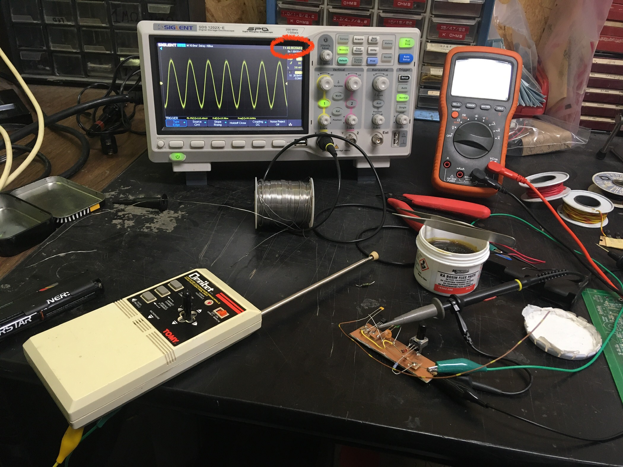
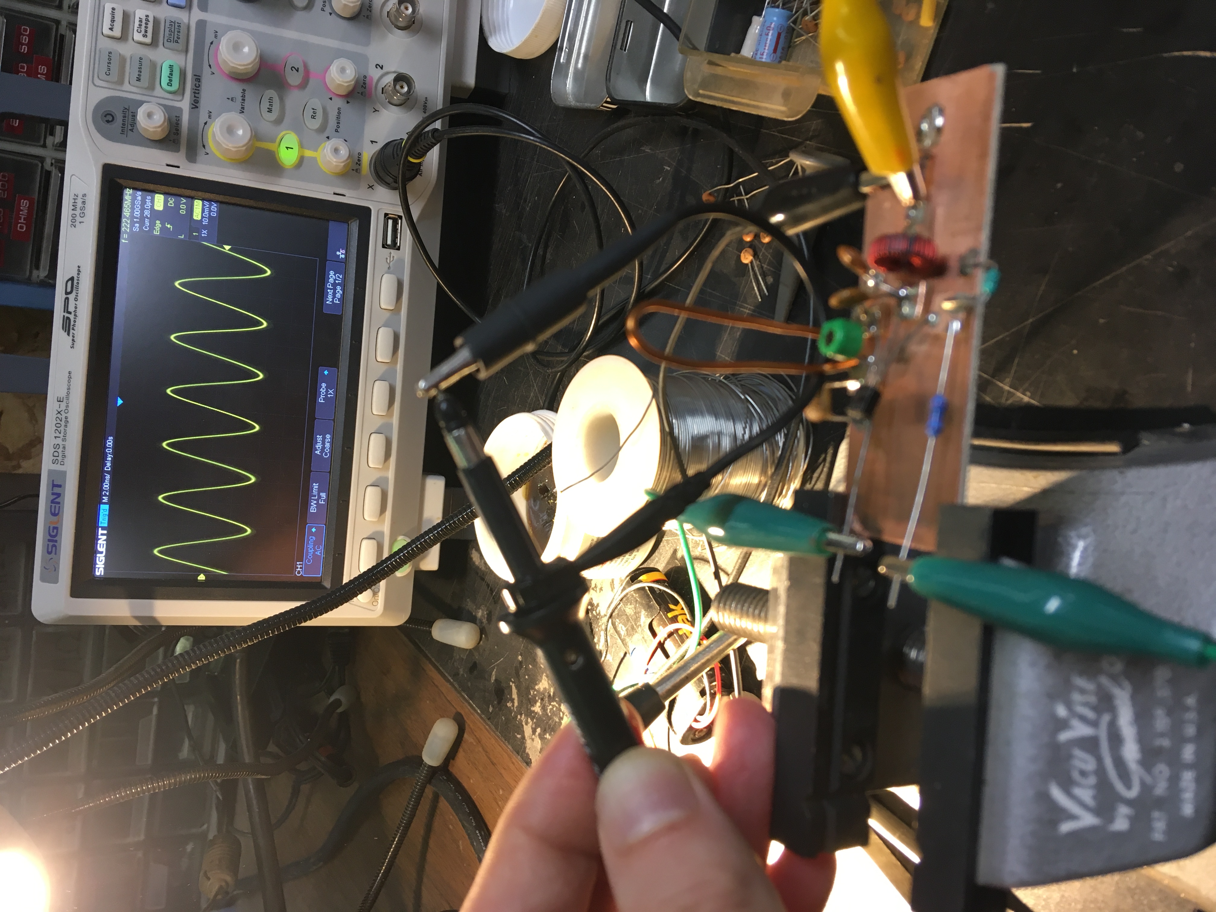
- In the text, L2 is recommended as a “ferrite bead with 3 turns of wire”. I didn’t find exactly that, so I used part of a small ferrite core transformer (see below the toroidal ferrite with ~50 turns of dark red wire). The reasoning was that L2 only serves to provide DC bias to the transistor and its precise value (AC response) is not too important. This turned out to cause problems! Read on…
Note the oscilloscope probe makes a small loop from the ground clip to the probe tip. At 300 MHz, even such a short length of wire is enough to pick up nearby signals. To physically touch the probe tip to the circuit would probably introduce so much parasitic capacitance that it would disturb the operating point of the oscillator and make the measurement meaningless.
The oscillator did start up, but the frequency (zoom in on the oscilloscope screen in the top right) was only around 220 MHz 😞, not nearly close enough to 300 MHz. What to do, what to do…
Increasing the Frequency
Recall that the resonant frequency of an LC circuit is given by:

That means that to increase the frequency, we must decrease L or C.
The original design calls for a “shorting bar” on L1; instead, I scraped the copper loop a little and soldered a shorting wire. This made it more difficult to adjust the inductance, but other parts of the circuit can be used for adjustment, too.
Theoretically, the trimmer capacitor C3 (in parallel with L1) is the one to adjust to control the operating frequency. However, the trimmer did not go low enough! Even after removing the capacitor entirely from the circuit, the frequency was still not high enough. There was probably so much coupling between different parts of the circuit, that this was driving up the effective capacitance in parallel with L1. Let’s try cutting down some other capacitances…
C1 and C2 are unlikely targets, as they are, by design, coupling those parts of the circuit to AC ground. C4 and C5, however, were probably contributing significantly to the lumped capacitance. C4 in particular was already a very small capacitor (5 pF if memory serves) and I didn’t have any parts smaller than that.
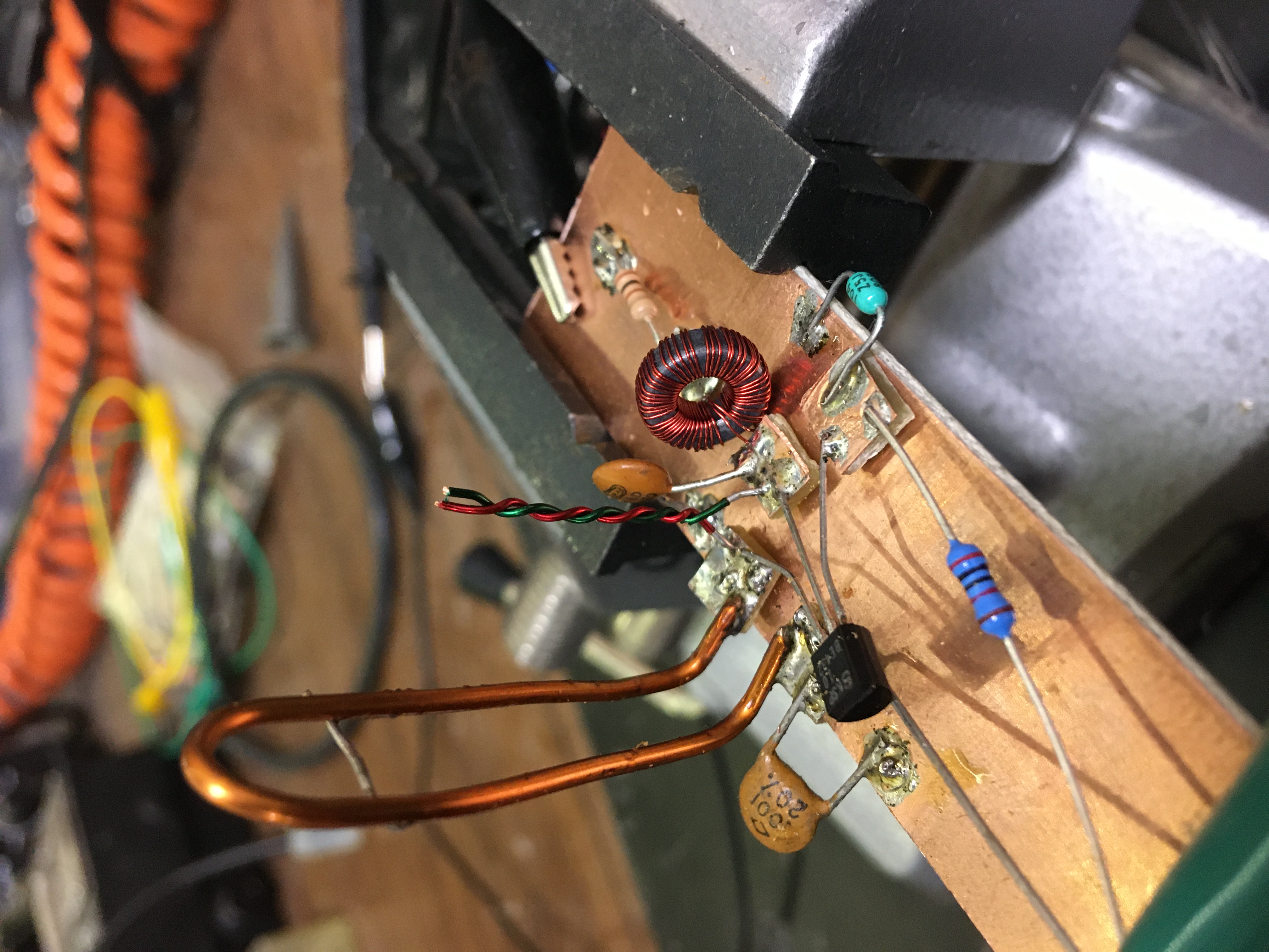
Let’s go back to first year physics - what’s a capacitor? Two conductors separated by an insulator. So I grabbed two short pieces of insulated magnet wire (from the dismantled transformer used for L2), twisted them, and soldered them in place of C4. It’s the pair of vertical twisted red and green wires in the center of the circuit and I call it a Christmas tree capacitor.
Lo and behold, it worked! The oscillation frequency went up to around ~308 MHz!
Modulation
Generating the base radio signal (carrier) is only the beginning. The goal is to turn it on and off (modulate) in a precise pattern, which the ceiling fan receiver would recognize as a particular command (toggle light, turn off fan, etc.). This is easy enough - program a microcontroller to send a sequence of pulses, and feed it into the transistor’s “base”. This will control the biasing of the transistor, effectively turning the amplifier on and off.
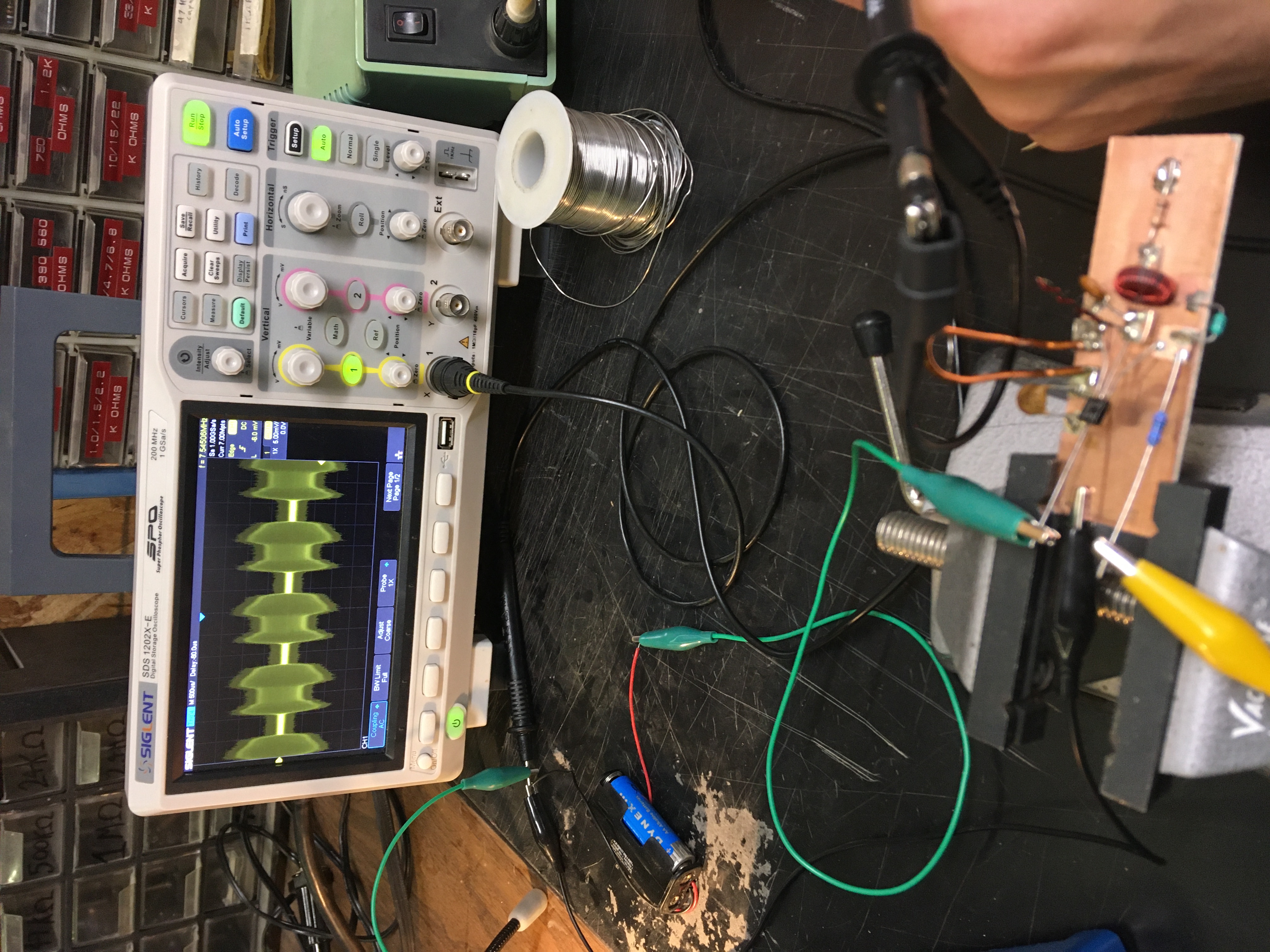
What microcontroller to use? The ESP32 from WiFi LoRA 32 (V2) above, of course! It’s a gross under-utilization of the capabilities of that board, but it works well. After uploading the program and connecting everything, I checked the shape of the output signal (photo to the right).
Gross! The envelope was unstable - the transmitter was not turning on and off steadily. This would probably affect the receiver’s ability to decode the signal. What could be the problem? My first thought went to the RF part of the circuit. Once the transistor was biased, maybe it was taking too long to amplify the oscillation to full amplitude. The explanation turned out to be more subtle (but easier to fix).
Take a look at the voltage across R2:
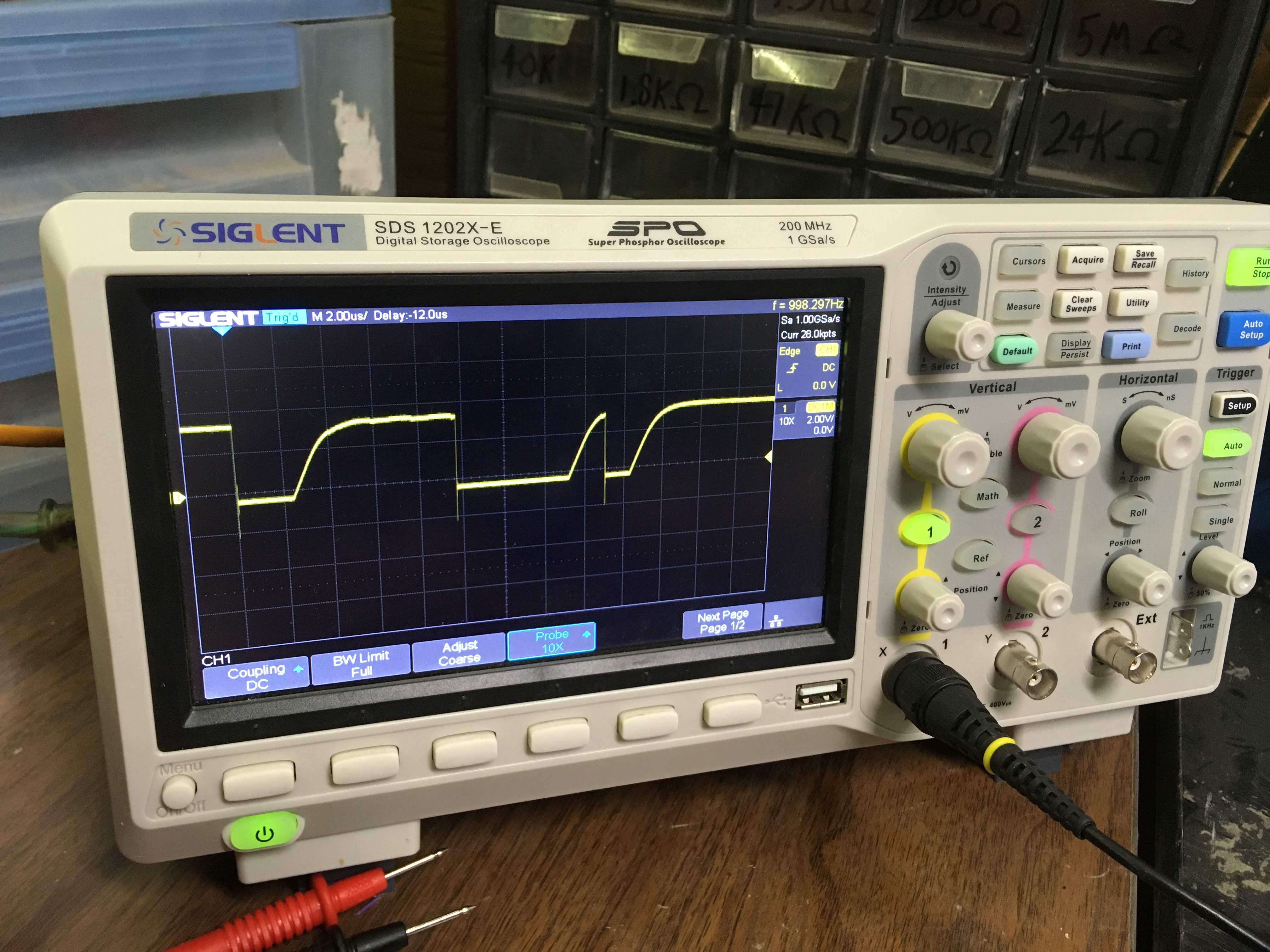
Due to L2, the waveform excludes any RF component and effectively shows the transistor bias only. Note the very slow rise times! The shape of those ramps looks suspiciously like a RC circuit step response. My first thought went to R1 and C1.
The RC circuit formed by R1 and C1 should have a time constant of 20 kΩ × 1 nF = 0.2 µs. However, the waveform showed a rise time of ~2 µs. That’s approximately one order of magnitude difference - R1 and C1 cannot be responsible for this artifact.
Hmm… what other circuit components are involved in the biasing, and may contribute to low-frequency response? What about R1 and L2? L2 was a “random inductor” with a fairly high number of turns, which would result in a high inductance, and high time constant. We need a compromise: L2 should respond quickly at the modulation frequency (~10 kHz) so that the transistor switches quickly and sharply; but L2 should also respond slowly at the RF oscillation frequency (300 MHz), so that it effectively isolates the RF from the rest of the circuit. The original design did recommend an inductor with a low number of turns…
Luckily, because these two frequencies are so far apart, it is not difficult to choose a good inductor for this. Scrounging through parts drawers, I found a ferrite core inductor with fewer (7 turns) and it worked wonderfully.

Fine-tuning the Frequency
Finally, the operating frequency (308 MHz) was still a bit too high for the receiver. I noticed that the circuit would work (as a test, toggle the ceiling fan light) only when I touched my hand to the inductor, as this would add a little parasitic capacitance and drag the frequency down. Now I needed to add a little capacitance to the circuit… I did not have good stock of small capacitors so I had to improvise.
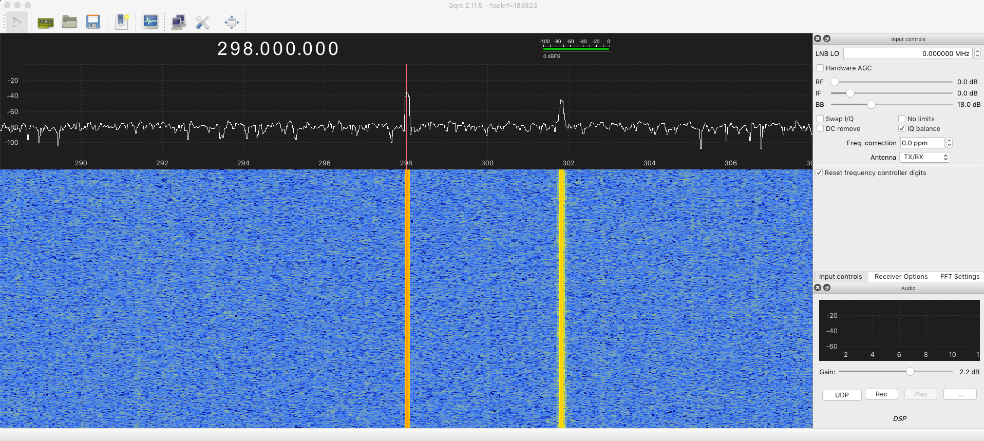
Previously I crafted the “Christmas tree capacitor” to add a small capacitance to the circuit - why not try that again. I twisted two thin insulated yellow wires and added them to the circuit. Unfortunately, it was too much! 😞 That dragged down the frequency to 298 MHz which was too low. So I untwisted the yellow wires (see photo above) and voilà, we had a cool ~301.8 MHz signal:
URH also showed a pretty clean modulated signal and was able to demodulate it:

And, bringing the microcontroller + transmitter combo to the fan, it managed to reliably toggle the fan light.
Writing the Arduino code to turn off the fan on a timer was an easy task compared to all of the above. But since it’s April and still cold outside, it will have to wait a few months before being truly put to the test!
Conclusion
Well, this was definitely one of my longest-running projects (almost two years end to end), but definitely one of the most interesting. It kept me just at the edge of my comfort zone, not too far in to get bored, but not too far out to get stuck. With a lot of research, freely available materials and guides, help from Foulab, friends, and lots of trial and error, I managed to pull it off.
If you want to see some of my other projects or reach out:
And come to Foulab Open Nights (every Tuesday 8pm), you’ll usually find me hunched over the electronics station.